Detail explanation about HP cone crusher
Introduction
The HP cone crusher is a compressive crusher in which feed material is crushed between a fixed bowl liner and a movable mantle.
Bigger rock particles are crushed directly between the surfaces of the mantle and bowl liner. This is called single layer crushing.
Smaller rock particles are crushed between other rock particles, which is termed multi-layer crushing or inter-particle comminution.
Multi-layer crushing plays a significant role in the HP cone crusher cavity. This improves the end product shape and reduces wear on the wear parts.
Basic concepts
1. Closed side setting (C.S.S.)
The closed side setting defines the reduction ratio in HP cone crusher and has a significant effect on the product gradation, capacity and power draw. The closed side setting is measured from the bottom of the mantle to the bottom of the bowl liner at their closest point during the gyrating cycle.
2. Feed opening
The feed opening defines the maximum feed size for a crushing cavity.
The closed side feed opening is the smallest distance between the top of the mantle and bowl liner as measured when they are at their closest to one another during their gyrating cycle.
The open side feed opening is the distance between the top of the mantle and bowl liner as measured when they are at their farthest from one another during their gyrating cycle.
In HP cone crusher standard cavities, the maximum feed size is approximately 80% of the open side feed opening. In HP cone crusher short head cavities, the maximum feed size is equal to the closed side feed opening.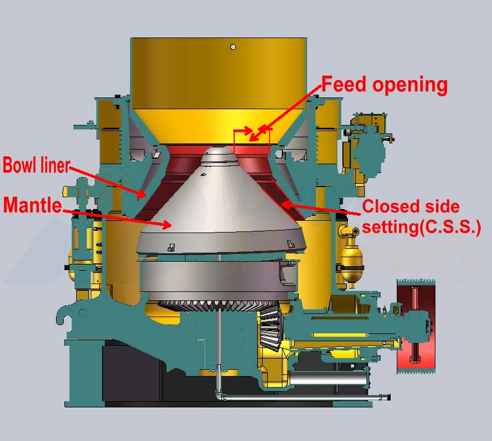
3. Nip angle
The nip angle is the angle between the mantle and bowl liner. Too large a nip angle reduces the capacity and increases the wear as feed material will tend to slip back upward in the cavity rather than crush. This can be observed as bouncing or boiling of the feed material.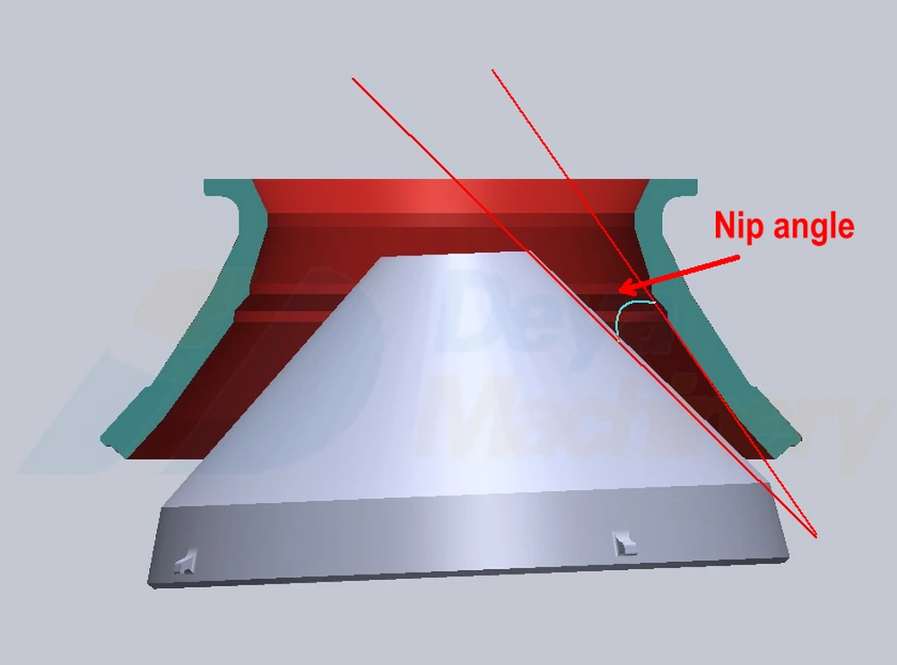
4. Reduction ratio
The reduction ratio is the ratio between the size of feed and the size of the outgoing product. It is normally measured at the 80% passing point.
A typical reduction ratio in the HP cone crusher standard cavity is 3-5 and in the HP cone crusher short head cavity it is 2-4.
How to operate a HP cone crusher correctly
In order to get optimum capacity and maximum wear life of wear parts, consider the following points when operate a HP cone crusher
1. Check the feed arrangement
• The crusher should be choke fed so that the crushing chamber is full all the time. This is important, especially in fine crushing.
Choke feeding maximizes the amount of multi-layer crushing, improves the shape of the crushing cavity as it wears and improves the crushing efficiency.
Choke feed level for an HP cone crusher is 300 mm or more above the feed plate.
• The feed must be distributed evenly 360º around the crushing chamber. Uneven feed distribution may cause power and force cycles through each gyration cycle.
Evenly distributed feed will result in a more steady power and crushing force.
• Feed should not be segregated, for example finer material on one side of the cavity and coarser material on the other side of the cavity.
• Flow of the feed should be stable and continuous
• Closed circuit crushing, where the crusher product goes to a screen and the oversize material returns to the crusher, is needed when producing high quality products.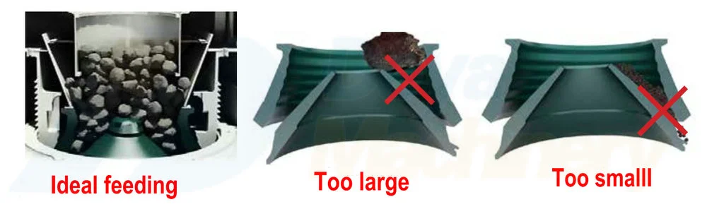
2. Check the feed size and gradation
• Oversize feed material decreases capacity and can cause abnormal wear of the liners
• Too small a feed size for the cavity increases the wear at the bottom part of the liners and may cause poor utilization of the wear parts
• Fine materials like 0-4 mm should be screened out before the material is fed to the crusher, because the fines may cause packing, they can be seen as adjustment ring movement which is a force overload.
• Feed should be well graded with no gaps in the size distribution.
3. Check the power draw
Crusher should operate with a steady power draw and as close to full rated power as practical, depending the circuit design and the ability to control system.
Note: Feed material characteristics such as gradation, bulk density, moisture, clay content and crushability have significant impact on crusher capacity.
4. Check the closed side setting
The setting should be close to the required product. The setting is too small if the adjustment ring is moving on the main frame.
Larger setting leads to increase of the the product size, capacity and power draw.
5. Check the crusher operating speed
Generally, a higher speed creates a finer product gradation curve and better product shape, which is important when producing the end product in most construction applications.
While operating the HP cone crusher at the lower end of its speed range will increase the cavity volumetric throughput and the product gradation curve can be altered to produce fewer fines.
The allowed speed limits can be found in the Deya Machinery’s HP cone crusher instruction manual. Before changing the speed of the crusher, consult Deya product support for further information.
6. Check the cavity in use
• Based on feed size
• Based on required end product size which determines the required setting range
• Check the crushing reduction ratio
7. Check the wear profile of the liners
A distorted wear profile may decrease capacity, increase the liner wear rate and increase the crushing force.
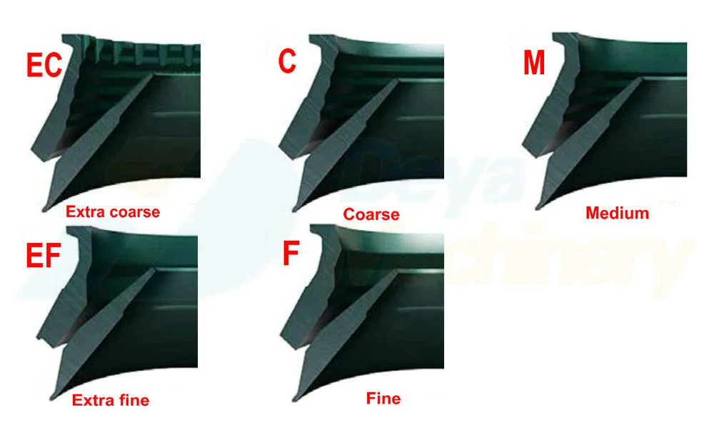
HP cone crusher cavity selection
Each HP cone crusher has several cavity options with different feed openings and setting ranges. The correct cavity can be selected based on the feed size, setting and application.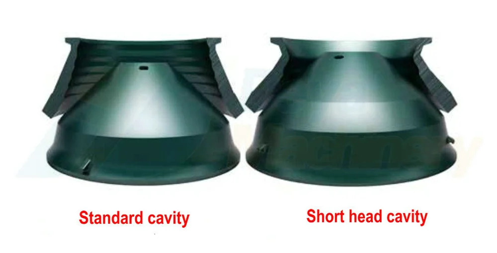
Standard liners are typically used in secondary applications. Secondary applications don’t necessarily need to be operated in closed circuit, but preferably choke fed.
Short head liners are used in tertiary or quaternary stage applications for fine crushing. Fine crushing requires choke feeding and closed circuit operation with oversize returning to the crusher.
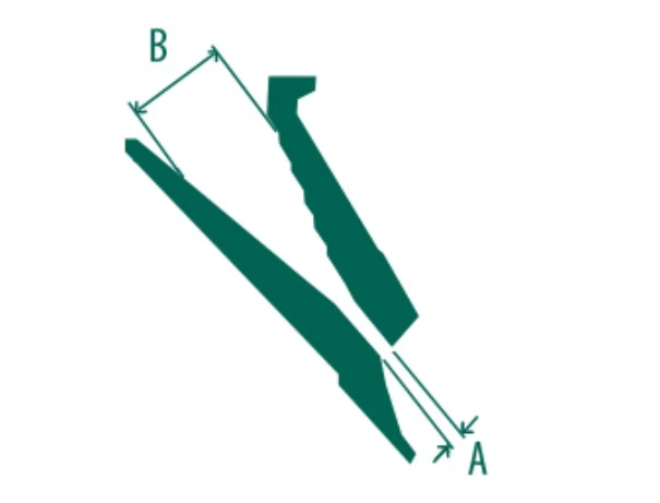
• The minimum setting is that at which the crusher will operate without causing ring bounce. Depending on the crusher characteristics of the rock, this setting can change.
• Feed opening “B” is at a minimum setting “A”.
• Maximum feed size vary from 80 to 100% of “B” depending on the machine size and material.
When to change liners
In order to avoid damage to the liner seating surfaces of the crusher head or bowl, wear parts must be replaced before they are worn through.
In normal conditions, approximately 50% of the liner weight is consumed when liners are worn out.
It is important to keep a record of liner wear in order to assess the degree of liner wear without the need to stop the crusher operation.
See the following instructions
1. On the initial set of new liners, place a mark on the adjustment cap driver ring where the pinion tooth makes contact with a driver ring tooth when the target crusher setting has been achieved.
2. Keep an accurate record of the number of teeth used to compensate for liner wear on this set of liners.
3. After the initial set of liners have worn out, but before moving the bowl, record the total number of teeth the driver ring has moved and also paint a horizontal liner on the side of the dust shell just below the bottom of the adjustment cap.
This will be the baseline for determining how close the next liner sets are to being worn out.
4. When a new liner set has been installed, keep a record of the number of teeth the driver ring has moved and compare this number to the total number from the initial set of liners. 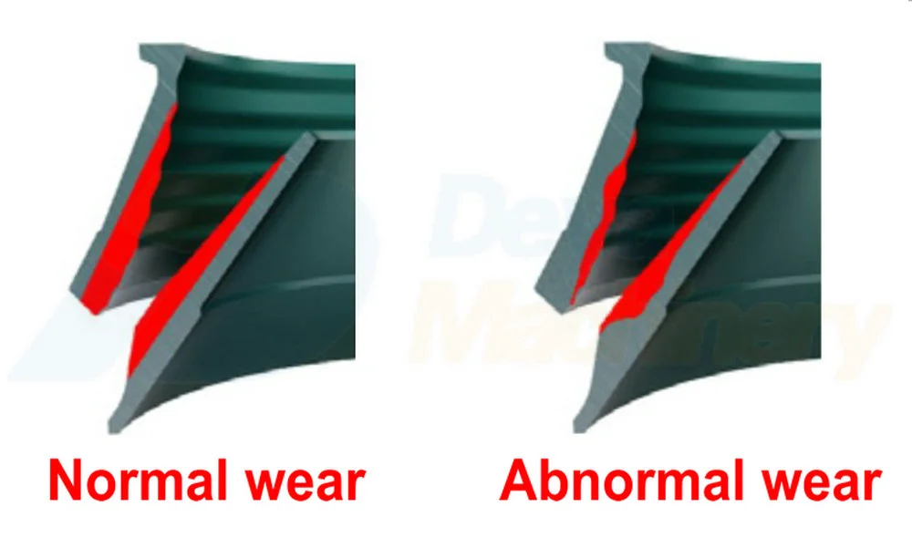
This will give an estimation of the liner wear. The horizontal mark painted on the dust shell will also indicated when the liners are approaching the wear limit.
The approximate minimum heights of the adjustment cap (A-dimension) with worn liners are listed in the attached tables.
When changing liners and determining liner wear, follow the instructions in the related Deya Machinery HP cone crusher instruction manual.
•Production considerations may sometimes favor changing of wear parts before they are fully utilized. Hourly capacity or product quality may decrease toward the end of the liner wear life and it may be more economical to change before the end of the liner wear life.
• Typically, distorted wear profiles can cause a reduction in capacity. Other symptoms of poorly worn liners are high power draw and ring bounce.
• Also, the wear life can be reduced because the wear is sometimes concentrated in a small zone rather than spread along the full cavity and the cavity may have to be replaced before they are fully worn.
This results in poor utilization and a higher operating wear costs.
Always contact Deya Machinery team when you have any trouble for the operation of HP cone crusher.
More about HP cone crusher
HP cone crusher regular maintenance and inspection
How to clear the crushing cavity of the HP cone crusher
Comprehensive guidelines for a new installed HP cone crusher initial operation