Comprehensive explanation about an impact crusher
Introduction
The impact crusher has a shaft that runs horizontally through the crushing chamber with a rotor that turns blow bars.
It uses the high speed impacting force of the turning blow bars projections to break the material.
With impact crushing, the material breaks along its natural cleavage lines, resulting in a more cubical product at high reduction ratios.
Impact crusher can be used as primary or secondary crushers.
In the primary stage, impact crushers are better suited for softer and less abrasive material.
In the secondary stage, the impact crusher can process more abrasive and harder material.
Linear speed
In compression crushing, like jaw crusher or cone crusher, the material is squeezed between 2 surfaces which get closer to each other. The crushing movement speed is between 0.5 m/s up to 1.5 m/s.
In impact crushing, the material is subject to shocks given by rotating parts and thrown against metal surfaces. The movement speed is from 30 up to 80 m/s.
Impact crushers are suitable for crushing hard rocks such as limestone, dolomite, granite and other similar materials under toughest operating conditions.
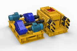
Construction of impact crusher
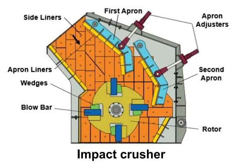
Above figure shows construction of a typical impact crusher. The rotor has wedge-shape grooves extending parallel to the shaft for holding blow bars.
The rotor shaft assembly is dynamically balanced to assure vibration free operation.
The rotor is equipped with two, four or six blow bars. The blow bars extend over the full width of the rotor. The bars are so designed that they can be used by turning them after one face wears out.
Two or three aprons (breaker plates) are positioned to form an arc of the circle centered to the point of impact. The first apron is normally fixed in initial crushing zone.
Liners (replaceable wear plates) are fitted to the aprons to ensure that the apron settings can be maintained.
Sometimes reversible and interchangeable mono-block type aprons are also provided. The housing/frame is fabricated from heavy steel plates and is stress relieved.
Inside surface of the housing is shielded/protected by the side/frame liners. Many times the housing is hydraulically hinged for its quick opening to reduce time required for maintenance.
Working principle
After entering the crushing radius of the rotor, the feeding material is broken by primary impact of the blow bars and the material propels towards the first apron (liners) where it is broken by secondary impact.
The material is then shot back from the apron to the blow bars. The material is also broken in the crushing chamber by material hitting material. Feed material is reduced approximately 60 % by initial impact with blow bars and 30 % by impact
with aprons.
The process repeats until the material is crushed to the required size and discharged through the discharge opening at the bottom of the machine.
The aprons can be adjustable by apron adjusters to compensation for wear of the blow bars and the aprons (liners). In order to prevent possible damage caused by any foreign bodies (tramp iron) entering the machine, the aprons are mounted on springs or hydraulic cylinders so that they can avoid any temporary overloads.
The size and shape of the end products also can be changed by changing the gap between the blow bars and the aprons by adjusting the apron adjustors. It may be noted that in small mobile machines, generally only one apron is provided.
Design Considerations
In design of an impact crusher, peripheral speed of the rotor, number of impact bars and metallurgy of the wear parts play an important role.
Rotor Speed
Increasing the rotor speed results in a tendency for a higher fine-particle proportion and in some cases, to greater output.
However, results in more wear of the blow bars. The wear doesn’t increase proportionally with the speed; it is a function of the square of the speed.
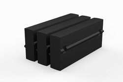
Number of Impact Bars
Generally, rotors with two or three blow bars are used for smaller crushing chamber geometries (inlet width of under 1100 mm with rotor diameter under 1100 mm). Larger crushing chamber geometries (inlet width over 1200 mm with rotor diameter over 1200 mm) are equipped with rotors having four or more blow bars.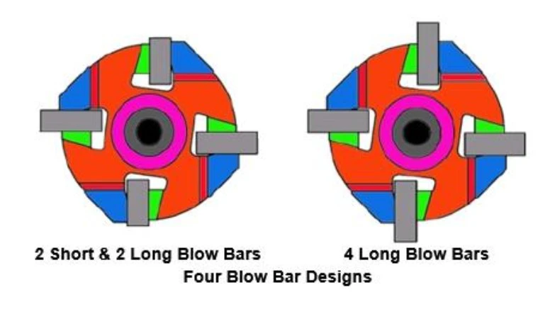
As shown in above figure, for a rotor with four blow bars, there are two designs in use: 2 short & 2 long blow bars and 4 long blow bars.
In design with 2 short & 2 long blow bars, time between blow bars is doubled improving penetration on material. It results in a higher tonnage for a given speed. It also produces less fines. This design is suitable for most applications.
However, design with 4 long blow bars is good for secondary applications where shape and size outweigh throughput. But this design produces more fines.
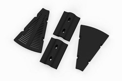
Material of Wear Parts
The impact elements; blow bars, apron liners and side/frame liners are made from wear resistant materials for long wear life.
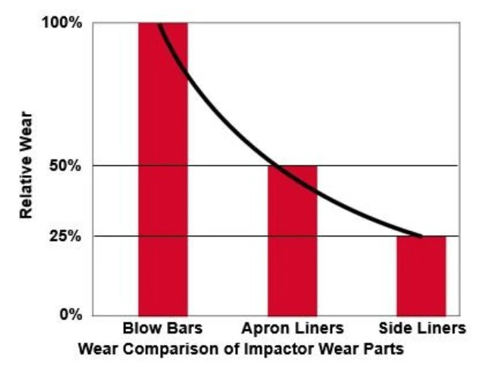
Above figure shows wear comparison of an impactor’s wear parts. The wear is maximum on the blow bars because the most reduction work takes place when the particles are struck by the blow bars. They account for about 60% of the total
wear costs.
Material of blow bars, apron liners and side/frame liners is chosen according to the material type, abrasion, foreign elements and size at the feeding and the required product. Typical material KmTBCr26, it is proved super performance in actual working.
Apron liners are made from either manganese steel castings or chromium iron.
Impact Crusher Feeding
Maximum feed size should be as per the manufacturers recommendations.
In primary impact crushing process, the physical size of the crusher feed opening must not be considered as the true gauge to set the maximum crusher feed size and, as a result of that, assess that any lump passing through the crusher feed opening has the correct feed size.
Significantly larger feed opening than recommended feed top size is recommended/provided to ease material flow and decreases bridging risks when several big lumps come at once.
The crusher should be started without load. Start feeding the material only after rotor attains the rated speed. Feeding of the crusher should be regulated one.
Choke feeding must not be done as it would create high wear and damages to the equipment. Fines from the feed
material should be removed before feeding the material to the crusher. Fines in the feed creates additional wear (if material is abrasive), rises risk of clogging if material is sticky and/or will generate additional dust emission. It may also require a larger crusher to achieve the same total production.
Impact crushers must always be fed on all width of the machine (80 to 90%) to ensure an even wear of the blow bars. Concentrated feed will generate localized wear of the blow bars. Typical case of a wrong feeding method is a direct material flow penetrating straight into the crushing chamber from a belt conveyor.
Note:
Crushed product has a high velocity when leaving the crushing chamber. Special care must be given to the design of the transfer point underneath the crusher, to prevent damages on collecting belt conveyor/vibrating feeder and to prevent excessive wear: stone box, thick chute liners wherever needed, sufficient headroom underneath the crusher.
Aprons Setting
The space (gap) between the aprons (breaker plates) and the blow bars permits only sized material to exit from the crusher.
Materials that are larger in dimension remain in the crushing cavity until the correct size is obtained. Then they are discharged.
Normally the crushing cavity is limited by two adjustable aprons (breaker plates), which control crushed product size and capacity.
The closer the aprons are to the blow bars, the smaller is the product size and the lower the capacity through the crusher.
The smaller the setting is, wearing is naturally faster. The further the aprons are from the blow bars, the higher is the throughput of the crusher, and the larger the product size.
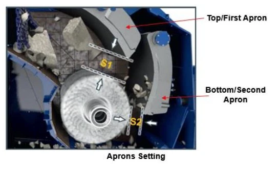
As shown in above figure, the bottom setting (S2) is the distance (gap) between the tip of the blow bar and the apron liner when the blow bar is facing the bottom/second apron liner.
The minimum operation/bottom setting (S2) depends on the size, the nature of the feed material and the capacity through the machine.
The bottom/second apron setting (S2) defines the size of the product discharged from the crusher (S2 = product size). In order to ensure the material flow and uniform filling of the crushing chamber, it recommended that the distance (gap) between the tip of the blow bar and the top/first apron liner (S1) should be approximately 30% of the maximum feed size.
Blow Bar Wear
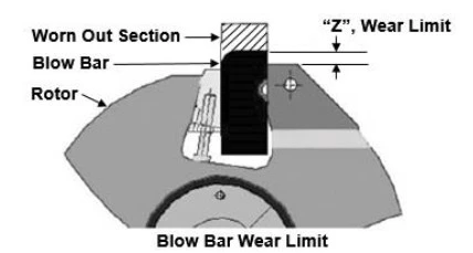
As shown in above figure, blow bar needs changed or rotated when the wear limit “Z” is reached otherwise considerable damage will occur to the rotor.
For the wear limit “Z”, please see the operation and maintenance manual supplied by Deya Machinery.
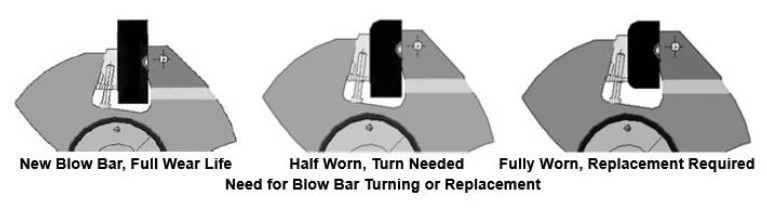
Blow bars are reversible. When one face is used, the blow bar can be turned around to use the other face.
Above figure shows when to turn or replace a blow bar.
It is recommended to change all 4 blow bars simultaneously. However, in some applications two worn blow bars and two new blow bars (diametrically opposed) may be used which works like a design with 2 short & 2 long blow bars.
To increase the life of blow bars the following guidelines should be adhered to:
Select correct blow bars depending on application.
Adjust machine parameters (rotor speed, gap, etc.) to match the application.
Maintain and clean crushing chamber daily.
Regularly inspect blow bars and take corrective action for premature wear or damage.
Blow Bar Replacement
A non-secured rotor can lead to severe injuries. Always observe safety instructions!
Completely extend the crusher gap before blow bar replacement in order to prevent a collision between the blow bars and the apron after new blow bars have been installed.
Make sure that all blow bars are in matched pairs pertaining to weight. The weight difference of paired blow bars should not exceed more than that recommended by the operation manuel of Deya Machinery. Normally the difference should not exceed 0.5 kg and the matched pairs should be installed on opposite sides of the rotor.
Before making the final settings, briefly operate the machine at the highest rotational speed and then check the wedge clamps. Tighten the screws if necessary.