Introduction
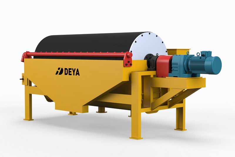
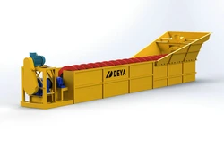
A magnetic separator is a device that uses magnetic properties to separate target minerals from other elements in minerals.
Magnetic separator is applicable for the magnetite, pyrrhotite, roasting ore, ilmenite, etc. with size less than 3 mm, it also can be used for removing iron in coal, non-metallic minerals, building materials and other materials.
According to user needs, Deya Machinery can provide different magnetic intensity for both dry and wet magnetic separators.
Features
• Strongest, most effective magnetic elements in the industry
• Ceramic and Rare Earth magnetic elements to cover various types of applications
• Stainless steel encapsulated magnetic element
• One piece stainless steel drum shell
• Abrasion–resistant aluminum or stainless steel end flanges
• Double row, self aligning ball bearings easily accessible without drum disassembly
Applications
Wet Drum Magnetic Separators can be used for increased efficiency in the following:
• Heavy media plants for recovery of magnetite or ferrosilicon
• Iron Ore concentration
• Extracting ferromagnetic material from various slurries
• Water Treatment Plants (Sirofloc Process)
Factors that affect the efficiency
1. Magnetic field strength. The magnetic field strength must be sufficient to effectively collect ferromagnetic minerals.
2. Hydraulic capacity. Ferromagnetic recovery is directly related to the flow rate through the separator. As the flow rate increases, the slurry velocity and consequently the fluid drag force increases which tends to detach more magnetite particles from the opposing magnetic field.
3. Percent solids. The percent solids of the feed directly affects the selectivity of the separation. As the percent solids increases, the slurry becomes more viscous minimizing the effects of the fluid drag to assist in the separation of the silica.
4. Ferromagnetic content. Any given wet drum magnetic separator has the characteristic of removing a limited amount of ferromagnetics based on the diameter of the drum, peripheral speed, and the magnetic field strength.
Structures
1. Magnetic system
The heart of the magnetic separator is the magnetic assembly. The magnetic element is the most important feature of a wet drum separator. Although there are several variables influencing magnetic separation, the magnetic field configuration is indisputably the foremost variable for high levels of magnetite recovery.
2. Adjustment of magnet and drum position
The position of magnetic drum and the angle of the magnetic assembly can easily be adjusted to obtain the best process performance. The adjustment possibilities include
• Magnet assembly positioning in relation to the concentrate discharge weir
• Horizontal position of the drum
• Vertical position of the drum
3. Feed Boxes
All feed boxes are normally made from mild steel and rubber lined. Other features of the feed boxes are:
• The feed box is integrated with the tank
• It discharges through a number of steel tubes into the separator tank
4. Drum drive system
Drive systems include chain and sprocket, synchronous belt, and shaft mounted direct. Motors are high efficiency. The standard bearing is a double row self aligning ball bearing that is greasable during operation.
Tank Design
There are three basic tank designs:
1. Concurrent
Concurrent tanks suit applications requiring high recoveries of medium with a high concentrate specific gravity. It enables the handling of slurries with particles up to 6mm in size.
2. Counter Flow
The Counter Flow design primarily caters for processes with surges in throughput. The tank configuration minimizes magnetic material losses in slurries with a high magnetics content, especially when a clean concentrate is not of prime importance.
Although the ideal material specification for this design is <0.5mm (-30 mesh) with a solids content of 30-40% by weight, the Counter Flow configuration handles materials with particles up to 4mm.
3. Counter Current
The Counter Current tank produces a high-grade magnetic concentrate, with lost fine magnetics passing into the tailings which are then re-processed to maximize magnetics recovery.
Technical data for wet process
| Model | Drum diameter | Drum length | Rotation speed | Feed size | Capacity | Power |
|---|---|---|---|---|---|---|
| mm | mm | RPM | mm | T/H | Kw | |
| CTB6012 | 600 | 1200 | <35 | 2-0 | 10-20 | 1.5 |
| CTB6018 | 600 | 1800 | <35 | 2-0 | 15-30 | 2.2 |
| CTB7518 | 750 | 1800 | <35 | 2-0 | 20-45 | 2.2 |
| CTB9018 | 900 | 1800 | <35 | 3-0 | 40-60 | 3 |
| CTB9021 | 900 | 2100 | <35 | 3-0 | 45-60 | 3 |
| CTB9024 | 900 | 2400 | <28 | 3-0 | 45-70 | 4 |
| CTB1018 | 1050 | 1800 | <20 | 3-0 | 50-75 | 5.5 |
| CTB1021 | 1050 | 2100 | <20 | 3-0 | 50-100 | 5.5 |
| CTB1024 | 1050 | 2400 | <20 | 3-0 | 60-120 | 5.5 |
| CTB1218 | 1200 | 1800 | <18 | 3-0 | 80-140 | 5.5 |
| CTB1224 | 1200 | 2400 | <18 | 3-0 | 85-180 | 7.5 |
| CTB1230 | 1200 | 3000 | <18 | 3-0 | 100-180 | 7.5 |
| CTB1530 | 1500 | 3000 | <14 | 3-0 | 170-280 | 11 |
Note: Base on different materials, feed size, magnetic intensity and other factors, the data will be different.
Technical data for dry process
| Model | CTG 7518 | CTG 9018 | CTG 1018 | CTG 1021 | CTG1024 | CTG 1230 | CTG 1530 |
| Drum size (mm) | 750X1800 | 900X1800 | 1050X1800 | 1050X2100 | 1050X2400 | 1200X3000 | 1500X3000 |
| Capacity (T/H) | 40 to 50 | 45 to 55 | 100 to 120 | 125 to 145 | 130 to 180 | 150 to 220 | 170 to 250 |
| Feed size (mm) | 0 to 8 | 0 to 8 | 0 to 8 | 0 to 10 | 0 to 10 | 0 to 10 | 0 to 10 |
| Motor (KW) | 3 | 4 | 5.5 | 5.5 | 5.5 | 7.5 | 11 |
| Water content | 0-3% | 0-3% | 0-3% | 0-3% | 0-3% | 0-3% | 0-3% |
| Rotation (r/m) | 34 | 30 | 24.5 | 24.5 | 24.5 | 21 | 18 |
Note: Base on different materials, feed size, magnetic intensity and other factors, the data will be different.

